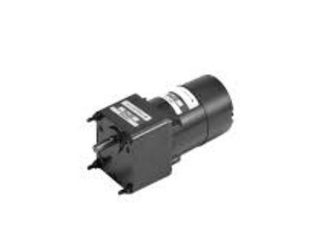
Debugging Method for Reversible Gear Reducer Motor Control Circuit
The debugging of a reversible gear reducer motor control circuit involves several key steps to ensure proper operation and avoid potential faults. Below are the main methods for debugging the control circuit of a reversible gear reducer motor:
1. Check the Main Circuit Wiring
- Ensure the wiring of the main circuit is correct. For the reliable switching of the motor’s phase sequence when both contactors are operating, the wiring should be configured such that the upper terminals of the contactors are wired consistently, while the lower terminals should be adjusted for phase alignment. This will allow the motor to properly reverse when needed.
2. Verify the Wiring
- Inspect all wiring connections to ensure they are correct. Before conducting a power-on test, first disconnect the motor wiring. This is necessary to prevent any accidents or short circuits during testing.
Troubleshooting for Reversible Gear Reducer Motor Faults
If the reversible gear reducer motor fails to operate correctly, certain faults and their causes should be considered. Below are common fault scenarios and their troubleshooting steps:
1. Motor Does Not Start
- Potential Causes:
- Blown Fuse: Check if the control fuse (FU) is blown. A blown fuse would prevent the motor from starting.
- Faulty Contacts: Inspect the thermal overload relay (FR) for faulty contacts or poor connection.
- Button Issues: Check if the normally closed (NC) contacts on the start/stop button (SB1) are faulty or worn out.
- Incorrect Wiring of Button Interlocks: If the interlocking wiring of the buttons is incorrect, it could prevent the motor from starting.
2. Abnormal Contactor Operation During Startup
- Cause: This issue is typically caused by incorrect wiring of the contactor’s normally closed (NC) interlock contacts. When starting the motor, the NC contacts initially close, energizing the contactor coil. However, as soon as the contactor is attracted, the NC contacts open again, de-energizing the coil and releasing the contactor. This cycle repeats, leading to abnormal contactor behavior.
- Solution: Verify and correct the interlock wiring of the contactor’s NC contacts to ensure smooth operation.
3. Incorrect Wiring of Self-Locking Contacts
- Cause: If the self-locking contacts (used for maintaining the contactor’s state once energized) are wired incorrectly, the motor may not operate as expected.
- Solution: Ensure that the self-locking circuit is wired properly, so the contactor remains energized once started.
By following these debugging steps and addressing the common faults listed, the reversible gear reducer motor control circuit can be properly adjusted to ensure efficient and safe operation. Always ensure proper wiring and conduct thorough testing before putting the system into full operation.

