Operation Principles and Features of Gear Reducers
Operation Principles:
A gear reducer primarily reduces the speed of the input shaft to provide lower speed and higher torque output. The working principle involves the meshing of gears to convert the high rotational speed of the motor into the required low speed, achieving a reduction in speed and an increase in torque.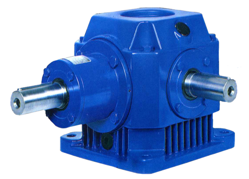
Main Features:
-
Compact Structure and Small Size: The coaxial helical gear reducer motor is designed to be compact, saving space while providing a visually appealing and robust structure with a strong overload capacity.
-
Precise Gear Ratios and Wide Selection Range: The transmission ratios of the reducer are finely graded, with a wide range of options available, from i=2 to 28800, to meet different application needs.
-
High Efficiency, Low Energy Consumption, and Low Noise: The efficiency of the reducer reaches up to 96%, effectively reducing energy consumption. It operates with minimal vibration and noise, making it suitable for noise-sensitive environments.
-
Versatility and Low Maintenance Costs: The reducer features a simple structure and is easy to maintain, especially suitable for production lines. By keeping a few key spare parts, it ensures the smooth operation of the entire production line, lowering maintenance difficulty and costs.
-
New Sealing Technology, Strong Environmental Adaptability: The reducer employs advanced sealing technology, which ensures stable operation in harsh environments (such as corrosive or humid conditions). It has excellent protection performance and strong adaptability to different environments.
Electromagnetic Speed Control Motor:
The electromagnetic speed control motor consists of three main parts: the driving motor, controller, and electromagnetic slip clutch. During operation, the motor starts running without load, and after a delay, the controller supplies current to the slip clutch’s excitation coil. This generates a magnetic field at the claw-shaped poles, inducing eddy currents in the armature. The interaction between the generated magnetic field and the original magnetic field drives the poles to rotate, producing torque. As the load increases, the excitation current also increases, thus raising the speed.
The controller compares the feedback signal (proportional to the speed of the output shaft) with the reference value. If the speed is below the desired level, the controller amplifies the voltage difference, increasing the excitation current to boost the speed. This process continues until the output speed matches the set value, at which point the controller stabilizes the output voltage, maintaining a constant speed of the motor shaft.
Key Technologies:
- Speed Control: The feedback mechanism adjusts the current and voltage through the controller to maintain a constant output shaft speed, adapting to load variations.
- No Mechanical Contact in the Electromagnetic Slip Clutch: The clutch operates via magnetic fields, avoiding mechanical wear and enhancing system durability and efficiency.