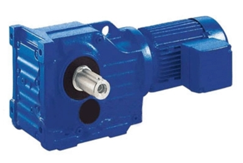
Part 1: Reduction Gear Speed Control Motor Pitch Adjustment Methods
1. Overview of Single-Phase Speed Control Motor Working Principle
Due to its structural limitations, a single-phase asynchronous speed control motor cannot start independently and requires additional devices for initiation. A common method involves integrating a starting winding (auxiliary winding) within the motor and adjusting the phase difference of currents in the main and auxiliary windings using capacitors or resistors to generate a rotating magnetic field.
Spatially, the axes of the main and auxiliary windings differ by 90° electrical degrees. When the phase difference of the currents in both windings also reaches 90°, a circular rotating magnetic field is generated, ensuring optimal startup and operational stability. If the current phase difference deviates from 90°, an elliptical rotating magnetic field forms, negatively impacting the motor’s starting capability and efficiency.
2. Definition of Pitch and Preparation Before Adjustment
Pitch (thread lead) refers to the axial distance between corresponding points of adjacent threads. Proper pitch adjustment is crucial for the stable operation of a speed control motor. Before making adjustments, the following preparatory steps should be completed:
- Ensure electronic equipment is properly debugged, with all channels connected correctly and in the proper direction.
- Disconnect the power supply to ensure safe operation.
- Remove the electrical impact wires and place them in a safe area to prevent accidental contact.
3. Pitch Adjustment Methods
Several methods can be used to adjust the pitch:
(1) Cross Plate Leveling Method
Adjust the pitch using a cross plate until it reaches a level state. Specific steps include:
- Loosen the pitch adjustment screws.
- Use a level gauge to measure the current pitch angle and adjust it to the standard value.
- Retighten the screws to secure the pitch in place.
(2) Phase Adjuster Method
Using the phase adjuster’s mixed control arm, auxiliary wing, day-shaped frame, and main rotor clamp, adjustments are made sequentially from bottom to top until the pitch is zero. Steps include:
- Select the appropriate phase adjuster mode.
- Adjust the mixed control arm to modify the current phase of the main and auxiliary windings.
- Fine-tune the angle using the day-shaped frame to ensure symmetrical positive and negative pitches.
(3) Master Rotor Calibration Method
Designating a master rotor as a reference point and adjusting only its pitch to minimize cumulative errors.
- Select and mark the master rotor.
- Measure the maximum and minimum pitch values. If deviations are significant, make gradual corrections.
- Ensure the final pitch error is within the permissible range.
(4) PITCH Value Adjustment Method
If significant pitch errors are observed, the PITCH value can be adjusted for correction.
- Calculate the difference between positive and negative pitch values, ideally 24.
- If the difference is less than 24, increase the PITCH setting to compensate for the error.
- Re-measure the pitch and fine-tune it until the final value meets specifications.

