The Principle of Gear Reducers
A gear reducer (also known as a gearbox or reduction gear) is a mechanical device that controls the output speed and torque of an electric motor by changing the rotational speed and torque. The basic principle of a gear reducer is to use gears to reduce the high-speed, low-torque output of the motor while increasing the output torque. Thus achieving speed reduction and enhancing torque transmission.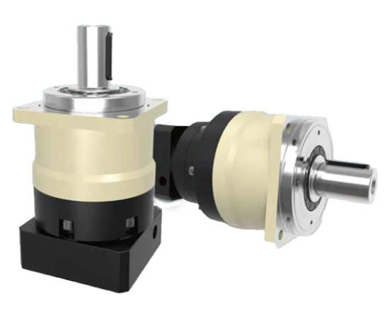
Working Principle of Gear Reducers
The working principle of a gear reducer relies on the gear transmission ratio. When the input shaft rotates, gears mesh with each other and transfer power, causing the output shaft to rotate at a lower speed while the torque increases. The gear reducer’s transmission ratio is determined by the size and number of the gears. The type and design of the gear reducer determine its load capacity and transmission efficiency.
Main Types of Gear Reducers
- Spur Gear Reducers: These reducers use spur gears to transmit power. They have a simple structure and high transmission efficiency, making them suitable for stable working conditions.
- Helical Gear Reducers: In these reducers, the gears have inclined teeth, which provides smoother transmission and lower noise levels, making them ideal for high-speed and high-load applications.
- Planetary Gear Reducers: These reducers utilize the combination of sun gears and planetary gears. This design offers higher reduction ratios and torque density, making them suitable for applications requiring high precision and efficient transmission.
- Worm Gear Reducers: Worm and worm wheels form the core of this reducer, which has a self-locking feature, making it suitable for applications that require prevention of reverse rotation.
Variable Frequency Drive (VFD) and Gear Reducers
In the field of electric motor reduction, variable frequency drives (VFD) are commonly used to control the speed of electric motors. The principle behind VFD is adjusting the frequency of the motor’s input power. However, the use of variable frequency drive technology in high-voltage and high-power applications presents limitations. This has led to the exploration of other speed control methods, such as chopper-based feedback control (chopper-controlled VFD), which also involves power control of the motor.
Power control in motor speed regulation generally involves two approaches:
- Electromagnetic Power Control: This method modifies the motor’s ideal no-load speed, providing a high-efficiency, energy-saving speed control.
- Loss Power Control: This method increases the motor’s speed drop, which typically results in lower efficiency and higher energy consumption, making it a less efficient, energy-consuming speed control method.
Integration of Gear Reducers and Motor Speed Control
Gear reducers and motor speed control systems work in tandem. The gear reducer reduces the output speed of the motor, while the motor speed control determines the operating state of the motor. The combination of these two elements provides the required output speed and torque for specific applications.
In summary, gear reducers change the motor’s speed and torque through gear systems, while motor speed control regulates the speed and power output of the motor. As industrial automation and energy efficiency requirements increase, developing efficient and controllable speed regulation methods—such as high-voltage AC speed control—has become a major area of research in the electric motor field.