Crossed Helical Gear Screw Gears
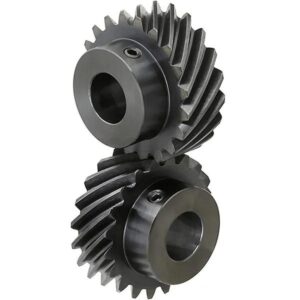
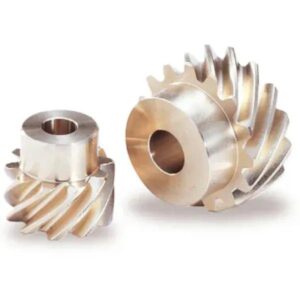
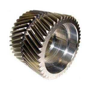
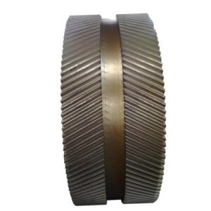
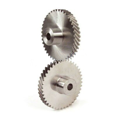
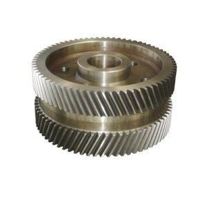
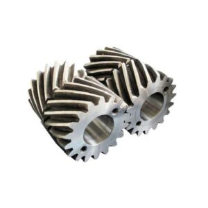
Crossed helical gears, also sometimes called screw gears, are helical gears used in motion transmission between non-intersecting shafts. The helical gears used in parallel shafts have the same helix angle but in opposite directions. An arbitrary helix angle can be chosen for shaft angles other than the parallel. Assuming no profile shift, the intersecting angle of the shafts is the sum of the respective helix angles. Crossed helical gears have point contacts and have lower efficiency than parallel or perpendicular shaft gears and cannot transmit heavy loads. Crossed helical gears are suitable for light load applications, machine tools, camshaft smell IC engines, etc.
Crossed Helical Gear (Screw Gears)
Crossed helical gears, also sometimes called screw gears, are helical gears used in motion transmission between non-intersecting shafts. The helical gears used in parallel shafts have the same helix angle but in opposite directions. An arbitrary helix angle can be chosen for shaft angles other than the parallel. Assuming no profile shift, the intersecting angle of the shafts is the sum of the respective helix angles. The crossed helical gears have point contacts and have lower efficiency than parallel or perpendicular shaft gears and cannot transmit heavy loads. And crossed helical gears are suitable for light load applications, machine tools, camshaft smell IC engines, etc.
 |
 |
Crossed Helical Gear Description
| Model Number | M1,M1.5,M2,M2.5,M3,M4,M5,M8,M12 and etc. |
| Material | Brass, C45 steel, Stainless steel, Copper, POM, Aluminum, Alloy, and so on |
| Surface treatment | Zinc-plated, Nickel plated, Passivation, Oxidation, Anodization, Geomet, Dacromet, Black Oxide, Phosphatizing, Powder Coating, and Electrophoresis. |
| Standard | ISO, DIN, ANSI, JIS, BS and Non-standard. |
| Precision | DIN6,DIN7,DIN8,DIN9. |
| Teeth treatment | Hardened, Milled, or Ground |
| Tolerance | 0.001mm-0.01mm-0.1mm |
| Finish | shot/sandblast, heat treatment, annealing, tempering, polishing, anodizing, zinc-plated |
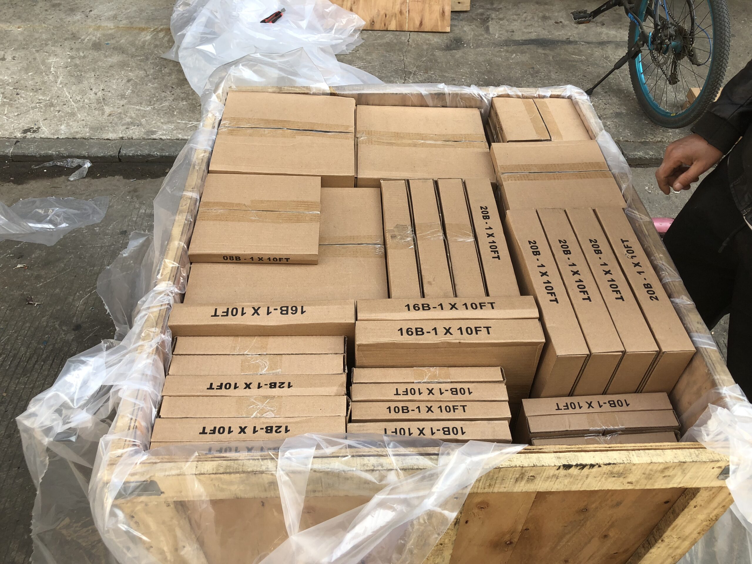
| Items packing | Plastic bag+Cartons Or Wooden Packing |
| Payment terms | T/T, L/C |
| Production lead time | 20 business days for the sample,25 days for the bulk |
| Samples | Sample price range from $2 to $100. sample express request paid by clients |
| Application | 1. Automatic controlling machine 2. Semiconductor industry 3. General industry machinery 4. Medical equipment 5. Solar energy equipment 6. Machine tool 7. Parking system 8. High-speed rail and aviation transportation equipment, etc. |
Crossed Helical Gear Design
- The geometry of crossed helical gears
- Crossed helical gear calculation
- Crossed helical gears with external and internal teeth
- Collision check
- Crossed helical gear with rack
- Fine sizing for crossed helical gear
Crossed Helical Gear Features
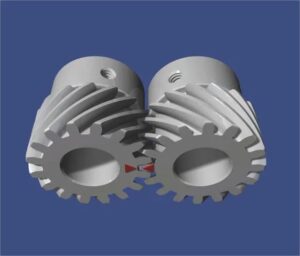
While the helix angles must be identical (but with the different hands of the helix) when pairing helical gears, paired crossed helical gears have different helix angles (but with the very hand of the helix). The transmission ratio depends on the ratio of these helix angles.
As the name suggests, the crossed helical gear no longer shows a pure rolling movement during the engagement but a screw motion. Typical for screw motions is the permanent sliding of the flanks. Thus, there are no points on the reference bodies of crossed helical gears to which a pure rolling process can be assigned (i.e., the circumferential speeds of the gears are not identical at any point). The reference bodies of crossed helical gear are no longer “pitch bodies” but so-called rotational hyperboloids! A hyperboloid is obtained by rotating a skew straight line around an axis.
The constant sliding of the flanks usually requires special lubrication of the crossed helical gears (hypoid gear oil); otherwise, increased wear is expected. Due to the screw course of the teeth, the flanks no longer touch each other line-shaped, but the contact is punctiform (exception: worm gears). In addition, the screw tooth path causes strong lateral forces, which must be absorbed constructively by an appropriate bearing.
Therefore, crossed helical gears are designed for moderate torques and speeds, e.g., for drives for machine tools. The use of crossed helical gear also has a disadvantageous effect on transmission efficiency, which is lower due to the sliding processes on the flanks.
The advantage of crossed helical gears, in addition to the already mentioned oblique arrangement of the gear axes, is their low-noise operation. In addition, crossed helical gears can be shifted axially within relatively wide limits without negatively influencing power transmission.
Differences Between Parallel Helical Gear and Crossed Helical Gear
| Parallel Helical Gear | Crossed Helical Gear |
|---|---|
| Parallel helical gears can transmit motion and power between parallel shafts only. | Crossed helical gears can transmit motion and power between perpendicular but not-intersecting shafts. |
| 2 mating gears must be mounted on two parallel shafts. | Two mating gears are mounted on two perpendicular but non-intersecting shafts. |
| Two mating gears should have the same helix angle but the opposite hand of the helix. | 2 mating gears may have different helix angles. They may have either same or the opposite hand of the helix. |
| Engagement between two teeth starts with a point contact but gradually becomes a line contact. | Two meshing teeth always have point contact. |
| The power transmission capacity of parallel helical gear is higher due to broader contact. | Crossed helical gear has lower power transmission capacity due to point contact. |
| It has many applications ranging from small equipment to large industrial fields, including gear trains. | It is rarely used in small-size instruments. |
 |
 |
Crossed Helical Gear Applications
Crossed helical gears are working on many lift/elevator and escalator-drive applications due to their compact size and the non-reversibility of the gear. Crossed helical gear is working in presses, rolling mills, conveying engineering, mining industry machines, on rudders. Crossed helical gear has lower power transmission capacity due to point contact. It has a wide area of applications ranging from small equipment to large industrial fields including gear trains. It is rarely working in small-size instruments.
Gear Transmission Maintenance
Proper maintenance is necessary for extending the service life of gears for ordinary working of gear transmissions. The daily maintenance mainly includes the following contents:
-
Installation and running-in. The fixing and positioning of the gears should meet the technical requirements during installation. Using a pair of new gears to run in first, that is, run for more than ten hours to dozens of hours under no-load and step-by-step loading. Then clean the box and replace it with new oil before use.
-
Proper use of gear transmission, start-up, loading, unloading, and gear shifting, should strive to be stable to avoid impact loads, and Party B is causing teeth to be broken and other failures.
-
Frequently check the condition of the lubrication system, such as the amount of lubricating oil, the state of oil supply, the quality of the lubricating oil, etc., to avoid the occurrence of impact loads, and regularly replace and supplement the lubricating oil of specified brand according to the user’s specifications.
-
Monitor the operating status, watch, touch, and hear for abnormal sounds if the cargo box is overheated, and “work with fault” is prohibited. For gear transmission at high speed, heavy loads, or on essential occasions, an automatic detection device can be adopted to ensure the safety and reliability of gear transmission.
-
Install the protective cover. For open gear transmission, the protective cover should be installed to prevent dust, chips, and other debris from entering the tooth surface, accelerating the wear of the tooth surface, and protecting personal safety.

Packing Shipping Delivery
  |
 |
|
 |
 |
|
How to choose power transmissions parts and industrial products which meet our requirement
| Chains | Sprockets | Pulleys | Timing belt Pulley | V-belt Pulley |
| Sheaves | Coupings | Bush &Hub | Gear& Rack | V-Belt |
| Locking Assembly | Pulley | Gearbox | Reducer | Shaft Collar |
| Rod End Bearing | Clevis | PTO | Chain Guide | Belt Guide |
| Rubber Buffer | Chain Tensioner | PTO Drive Shafts | Universal Joints | Roller Chains |
| Conveyor Chains | V-Belts | Worm Gearbox | Helical Gear | Worm |
| Agricultural Chain | CNC Proces Parts | Casting | Stamping | |
| Powder Metallurgy | CNC Proces Parts | Casting | Stamping |
What Products Do you sell ?
We are a group of factories, give customer one stop solution of power transmission and industrial products. We are in the position to supply wide range of products, including chains, sprockets, v-belt and v-belt pulleys, timing belt and timing belt pulleys, gears, speed reducers, motors, racks, couplings, and many other parts, like locking assembly, taper bushing, Chain guide, shaft collar, torque limiter, cam clutch, universal joint, motor base and motor slide, rod end, clevis, rubber mount, etc. We make special parts according to drawings and/or samples.
How to choose a gearbox which meets our requirement?
You can refer to our catalogue to choose the gearbox or we can help to choose when you provide
the technical information of required output torque, output speed and motor parameter etc.
What information shall we give before placing a purchase order?
a) Type of the gearbox, ratio, input and output type, input flange, mounting position, and motor informationetc.
b) Housing color.
c) Purchase quantity.
d) Other special requirements.
What industries are your gearboxes being used?
Our gearboxes are widely used in the areas of textile, food processing, beverage, chemical industry,
escalator,automatic storage equipment, metallurgy, tabacco, environmental protection, logistics and etc.
What is the producing process?
Production process including raw material cutting, machine processing, grinding, accessories cleaning, assemble, cleaning, stoving, oil coating, cover pressing, testing, package.
How to control the products quality?
Combining advanced equipment and strict management, we provide high standard and quality bearings for our customers all over the world.
What is the transportation?
-If small quantity , we Suggest to send by express, such as DHL,UPS, TNT FEDEX. If large amount, by air or sea shipping.
Can we design packaging?
-Yes. Default is regular packing, and we can make customer's own packing.
Can you provide OEM service?
-Yes, we work on OEM orders. Which means size, quantity, design, packing solution, etc will depend on your requests; and your logo will be customized on our products.
Can you give me discount on Power Transmissions Parts and Industrial parts?
-Yes, of course. Pls. send me your Email, you'll get more
Q: Are You a trading company or a manufacturer?
A: We Are the factory and have our Own trading company
Q: How Can I get an offer?
A: please send US quotation information: drawings, materials, weight, quantity and requirements, we can accept PDF, ISGS, DWG, STEP file format. If you don't have the drawings, please send us the samples, we can also quote you according to your samples.
Q: What is your minimum order size?
A: it is usually 100 pieces, but a low quantity is acceptable under some special circumstances.
Q: Do you provide samples? Is it free or extra?
A: Yes, we can provide samples free of charge, but we don't pay the freight.
Q: What is the lead time for mass production?
A: honestly, it depends on the number of orders. Normally, if you don't need the tools, deposit them after 30 days or so.
Q: What if the parts don't Work?
A: we can guarantee the quality, but if it happens, please contact us immediately, take some photos, we will check the problem and solve it as soon as possible.
Q: What are your terms of payment?
A: payment is less than US $1000,100% in advance. Payment: $1000,50% wire transfer in advance, balance before shipment,Other Terms of payment are negotiable




Reviews
There are no reviews yet.