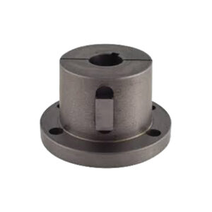
G Split Taper Bushings
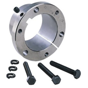
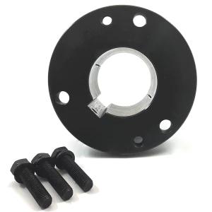
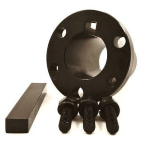
Tapered bushings(G Split Taper Bushings) are used in a wide variety of applications. They are often used in power transmission components such as shafts attached to rollers or pulleys. These tapered bushings feature a wedge action handle for easy locking and removal without deforming the shaft. There are two main types of tapered bushings: QD and Taper-Lock. Each of them has a specific hub size and a different type of locking mechanism.
Type QD has a straight flange around the tapered OD and is fully split. These tapered bushings use hex head screws to tighten the installed assembly onto the bushing and compress the inside diameter to fit the key shaft tightly. G Split Taper Bushings are the most common and versatile of all types of tapered bushings.
Dimensions of G split taper bushing
- Bushing Type: G
- Bore Size: 10mm、11/16″、11mm、14mm、15/16″、16mm、18mm、19mm、20mm、22mm、24mm、25mm、7/16″、9/16″
- Dimension (L): 1″
- Dimension (U): 1/4″
- Dimension (T): 3/4″
- Large End Dimension (D): 1.172″
- Small End Dimension (D): 1.133″
- Dimension (H): 2″
- Dimension (V): 1-9/16″
- Dimension (X): 5/8″
- Dimension (Y): 3/16″
- Dimension (R): 1/8″
- Dimension (S): 3/16″
- Cap Screws Amount: 2
- Cap Screw Size: 1/4″ X 5/8″
- Wrench Torque: 95 LBS
- Weight: 0.5 LBS
Common uses of G-split tapered bushings
Some common uses for G Split Taper Bushings are listed below. They are used in various applications such as drive shafts and sprockets. They feature a wedge-action tapered grip, which allows them to hold without deforming the shaft and is easy to remove. G Split Taper Bushings are available in different sizes and types. The most common are QD bushings and Taper-Lock bushings.
XTB15, XTB20, and XTB25 Split Taper Bushings are available in Metric and Imperial. They are available in metric and inch and have different keyway sizes. The XTB120 is the smallest diameter tapered bushing with a one-inch wide hole. These sleeves are available in different sizes including G, H, and P1 keying. They also enter Y0.
Installation
1. Make sure the bushing cone and interior of the driven product are clean and free of anti-seize lubricant.
2. Place the bushing into the sprocket or other part type that accepts bushings.
3. Loosely place the cap screws into the pull-up holes. The bushing remains loose to ensure a slip fit on the shaft.
4. Using the keys on the shaft, slide the sprocket or other part type to the desired position on the shaft. Make sure that the heads of the cap screws are accessible.
5. Align the sprockets or part types, alternately and incrementally tighten the screws until they are taut. Do not use extensions on the wrench handle, and do not allow sprockets or parts to be pulled out and contact the bushing flange. There should be a gap between the bushing flange and the sprocket at this point to ensure that the gap does not close.
Removal
1. Loosen and remove cap screws.
2. Insert the cap screws into the threaded removal holes.
3. Tighten the inserted screws until the sprocket or other part type is loose on the shaft.
4. Remove sprocket/part type from the shaft.
Click and check out more products you’re looking for.
Q1. Are you a factory?
A. Yes. We are a factory with more than 30 years of manufacturing experience.
Q2. Is OEM and ODM service available?
A. Of course. We have many years of experience in OEM& ODM service.
Q3. I am buying from another supplier, but need better service. Would you match or beat the price I am paying?
A. We always think we provide the best service and competitive price. We would be happy to provide you with a personalized competitive quote, email us.

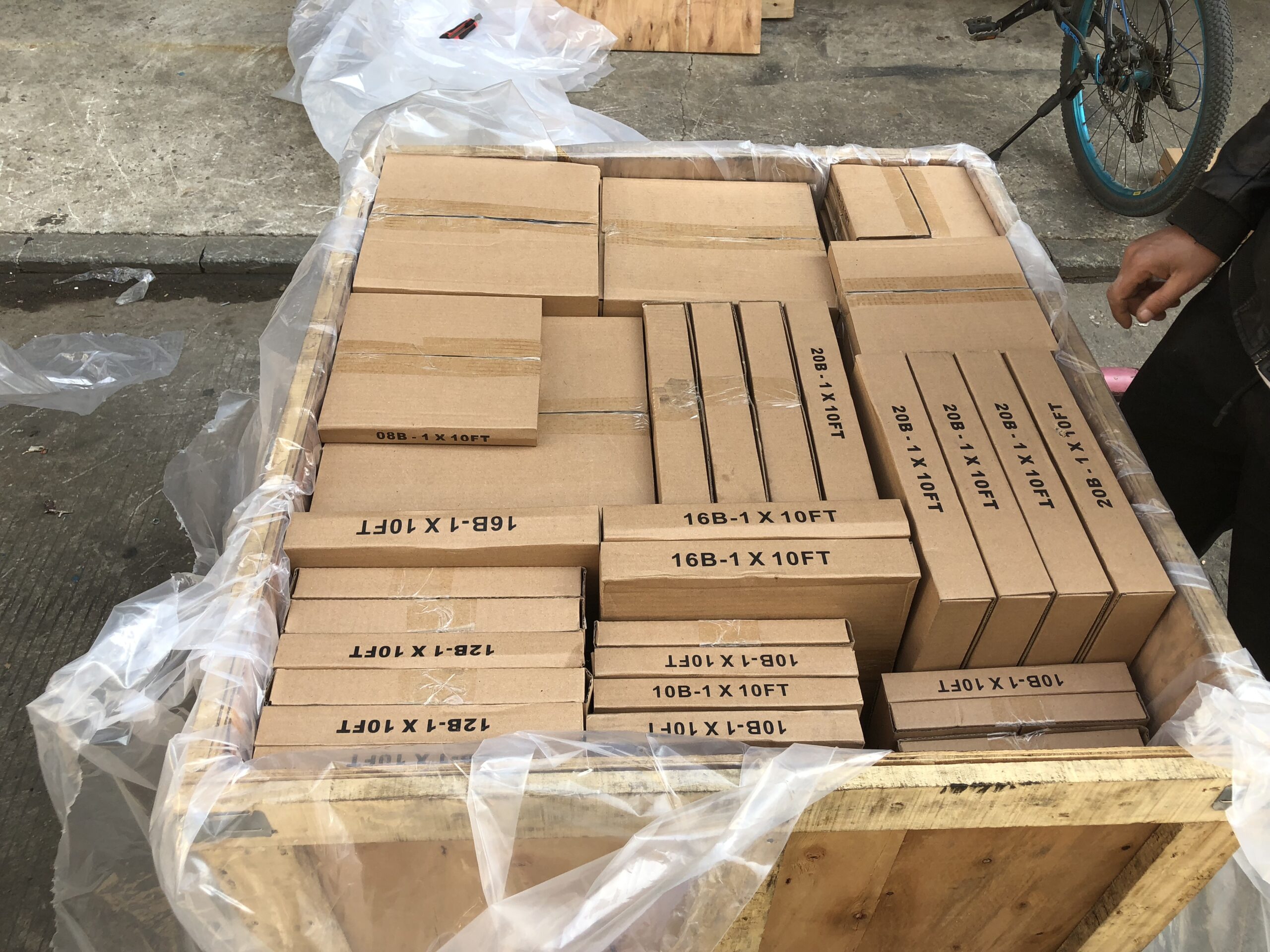
Packing Shipping Delivery
  |
 |
|
 |
 |
|
How to choose power transmissions parts and industrial products which meet our requirement
| Chains | Sprockets | Pulleys | Timing belt Pulley | V-belt Pulley |
| Sheaves | Coupings | Bush &Hub | Gear& Rack | V-Belt |
| Locking Assembly | Pulley | Gearbox | Reducer | Shaft Collar |
| Rod End Bearing | Clevis | PTO | Chain Guide | Belt Guide |
| Rubber Buffer | Chain Tensioner | PTO Drive Shafts | Universal Joints | Roller Chains |
| Conveyor Chains | V-Belts | Worm Gearbox | Helical Gear | Worm |
| Agricultural Chain | CNC Proces Parts | Casting | Stamping | |
| Powder Metallurgy | CNC Proces Parts | Casting | Stamping |
What Products Do you sell ?
We are a group of factories, give customer one stop solution of power transmission and industrial products. We are in the position to supply wide range of products, including chains, sprockets, v-belt and v-belt pulleys, timing belt and timing belt pulleys, gears, speed reducers, motors, racks, couplings, and many other parts, like locking assembly, taper bushing, Chain guide, shaft collar, torque limiter, cam clutch, universal joint, motor base and motor slide, rod end, clevis, rubber mount, etc. We make special parts according to drawings and/or samples.
How to choose a gearbox which meets our requirement?
You can refer to our catalogue to choose the gearbox or we can help to choose when you provide
the technical information of required output torque, output speed and motor parameter etc.
What information shall we give before placing a purchase order?
a) Type of the gearbox, ratio, input and output type, input flange, mounting position, and motor informationetc.
b) Housing color.
c) Purchase quantity.
d) Other special requirements.
What industries are your gearboxes being used?
Our gearboxes are widely used in the areas of textile, food processing, beverage, chemical industry,
escalator,automatic storage equipment, metallurgy, tabacco, environmental protection, logistics and etc.
What is the producing process?
Production process including raw material cutting, machine processing, grinding, accessories cleaning, assemble, cleaning, stoving, oil coating, cover pressing, testing, package.
How to control the products quality?
Combining advanced equipment and strict management, we provide high standard and quality bearings for our customers all over the world.
What is the transportation?
-If small quantity , we Suggest to send by express, such as DHL,UPS, TNT FEDEX. If large amount, by air or sea shipping.
Can we design packaging?
-Yes. Default is regular packing, and we can make customer's own packing.
Can you provide OEM service?
-Yes, we work on OEM orders. Which means size, quantity, design, packing solution, etc will depend on your requests; and your logo will be customized on our products.
Can you give me discount on Power Transmissions Parts and Industrial parts?
-Yes, of course. Pls. send me your Email, you'll get more
Q: Are You a trading company or a manufacturer?
A: We Are the factory and have our Own trading company
Q: How Can I get an offer?
A: please send US quotation information: drawings, materials, weight, quantity and requirements, we can accept PDF, ISGS, DWG, STEP file format. If you don't have the drawings, please send us the samples, we can also quote you according to your samples.
Q: What is your minimum order size?
A: it is usually 100 pieces, but a low quantity is acceptable under some special circumstances.
Q: Do you provide samples? Is it free or extra?
A: Yes, we can provide samples free of charge, but we don't pay the freight.
Q: What is the lead time for mass production?
A: honestly, it depends on the number of orders. Normally, if you don't need the tools, deposit them after 30 days or so.
Q: What if the parts don't Work?
A: we can guarantee the quality, but if it happens, please contact us immediately, take some photos, we will check the problem and solve it as soon as possible.
Q: What are your terms of payment?
A: payment is less than US $1000,100% in advance. Payment: $1000,50% wire transfer in advance, balance before shipment,Other Terms of payment are negotiable



Reviews
There are no reviews yet.