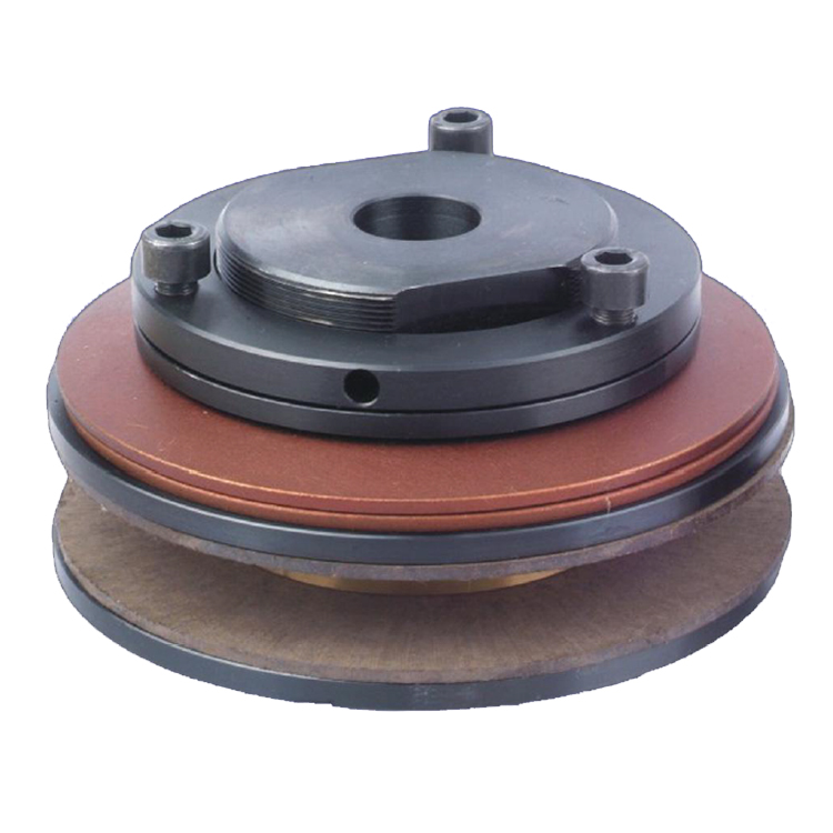
Torque Limiter
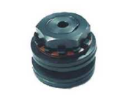 |
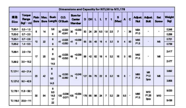
TL50-1 TL50-2
|
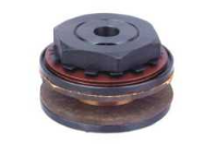 |
TL65-1 TL65-2
TL89-1 TL89-2
|
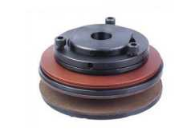 |
TL127-1 TL127-2
TL178-1 TL178-2
|

 Name of parts:
①Hub ②Friction Facing ③Bushing ④Pressure Plate
⑥Pilot Plate ⑦Adjustment Nut ⑧Adjustment Bolt ⑨Set Screw
⑤Disc Spring 10.Lock Washer
1.Determine the required slip torque from the loading conditions or from the design strength of the machine. If the loading conditions of the machine are unknown, set the required slip torque of the torque limiter to 1.5 ~ 2 times the torque the motor produces on the shaft where the torque limiter is mounted.
2.Select a torque limiter that has enough torque range and bore range.
3.Determine the proper bushing length from the thickness of the center member to be inserted between the friction facings. Always choose the largest bushing which does not exceed the width of the center member being shown as max.” in the dimension table.
1.The center member should be machined on its rubbing surface to obtain the rated torque and be flat, parallel, square with bore, and free from rust, scale, and oil. Surface finish recommended is Ra 1.6. If the center member is not in accordance with these specifications, the slip torque will be erratic.
2.Bore of the center member to be machined is shown in the table below. Also, min. numbers of sprockets teeth to be used and bushing length to be chosen are listed in this table.
Minimum Sprocket Teeth and Bushing Length
 TORQUE SETTING
- Torque setting of the torque limiter is achieved by tightening or loosening the adjustment bolts and/or the adjustment nut. For torque adjustment of TL50 through TL89 , an adjustment nut is provided, and for TL127 through TL178 , adjustment bolts are provided.
- The torque setting can be made after mounting the torque limiter on the shaft. The process is:
- For TL50 through TL89,
First, rotate the adjustment nut tightly by hand so that the disk spring can fit the plate. Then tentatively tighten the nut by about 60 degrees with a wrench.
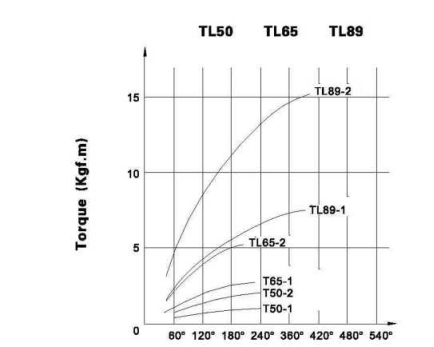
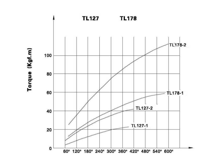
Rotated Angle and Setting Torque
Rotated Angle (degree)
- For TL127 through TL178,
First, rotate the nut for fixing the disk spring to the plate, and then tighten each adjustment bolt by about 60 degrees. Then, if the torque limiter slips under normal loading conditions, tighten the nut (for TL50 ~ TL89) or the bolts (for TL127 ~ TL178) gradually until the
torque limiter stops slipping. Always tighten (or loosen) the bolts equally. Try this adjustment several times to find the proper torque setting for the machine. For your guidance, the below chart shows the relation between the effective rotated angle and preset torque.
For precise torque setting, run-in of the torque limiter is recommended, for example, 500 revolution at 50 ~ 60 rpm with a rotated angle of 45 degrees of the adjustment nut or the bolts.
Rotated Angle (degree)

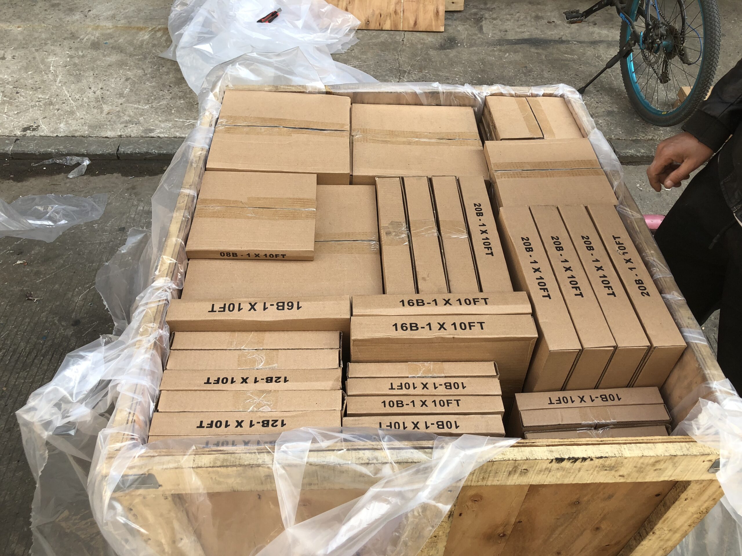
Packing Shipping Delivery
  |
 |
|
 |
 |
|
How to choose power transmissions parts and industrial products which meet our requirement
| Chains | Sprockets | Pulleys | Timing belt Pulley | V-belt Pulley |
| Sheaves | Coupings | Bush &Hub | Gear& Rack | V-Belt |
| Locking Assembly | Pulley | Gearbox | Reducer | Shaft Collar |
| Rod End Bearing | Clevis | PTO | Chain Guide | Belt Guide |
| Rubber Buffer | Chain Tensioner | PTO Drive Shafts | Universal Joints | Roller Chains |
| Conveyor Chains | V-Belts | Worm Gearbox | Helical Gear | Worm |
| Agricultural Chain | CNC Proces Parts | Casting | Stamping | |
| Powder Metallurgy | CNC Proces Parts | Casting | Stamping |
What Products Do you sell ?
We are a group of factories, give customer one stop solution of power transmission and industrial products. We are in the position to supply wide range of products, including chains, sprockets, v-belt and v-belt pulleys, timing belt and timing belt pulleys, gears, speed reducers, motors, racks, couplings, and many other parts, like locking assembly, taper bushing, Chain guide, shaft collar, torque limiter, cam clutch, universal joint, motor base and motor slide, rod end, clevis, rubber mount, etc. We make special parts according to drawings and/or samples.
How to choose a gearbox which meets our requirement?
You can refer to our catalogue to choose the gearbox or we can help to choose when you provide
the technical information of required output torque, output speed and motor parameter etc.
What information shall we give before placing a purchase order?
a) Type of the gearbox, ratio, input and output type, input flange, mounting position, and motor informationetc.
b) Housing color.
c) Purchase quantity.
d) Other special requirements.
What industries are your gearboxes being used?
Our gearboxes are widely used in the areas of textile, food processing, beverage, chemical industry,
escalator,automatic storage equipment, metallurgy, tabacco, environmental protection, logistics and etc.
What is the producing process?
Production process including raw material cutting, machine processing, grinding, accessories cleaning, assemble, cleaning, stoving, oil coating, cover pressing, testing, package.
How to control the products quality?
Combining advanced equipment and strict management, we provide high standard and quality bearings for our customers all over the world.
What is the transportation?
-If small quantity , we Suggest to send by express, such as DHL,UPS, TNT FEDEX. If large amount, by air or sea shipping.
Can we design packaging?
-Yes. Default is regular packing, and we can make customer's own packing.
Can you provide OEM service?
-Yes, we work on OEM orders. Which means size, quantity, design, packing solution, etc will depend on your requests; and your logo will be customized on our products.
Can you give me discount on Power Transmissions Parts and Industrial parts?
-Yes, of course. Pls. send me your Email, you'll get more
Q: Are You a trading company or a manufacturer?
A: We Are the factory and have our Own trading company
Q: How Can I get an offer?
A: please send US quotation information: drawings, materials, weight, quantity and requirements, we can accept PDF, ISGS, DWG, STEP file format. If you don't have the drawings, please send us the samples, we can also quote you according to your samples.
Q: What is your minimum order size?
A: it is usually 100 pieces, but a low quantity is acceptable under some special circumstances.
Q: Do you provide samples? Is it free or extra?
A: Yes, we can provide samples free of charge, but we don't pay the freight.
Q: What is the lead time for mass production?
A: honestly, it depends on the number of orders. Normally, if you don't need the tools, deposit them after 30 days or so.
Q: What if the parts don't Work?
A: we can guarantee the quality, but if it happens, please contact us immediately, take some photos, we will check the problem and solve it as soon as possible.
Q: What are your terms of payment?
A: payment is less than US $1000,100% in advance. Payment: $1000,50% wire transfer in advance, balance before shipment,Other Terms of payment are negotiable


 Name of parts:
 TORQUE SETTING
Reviews
There are no reviews yet.