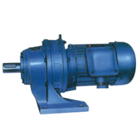
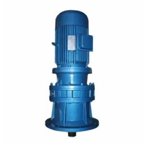
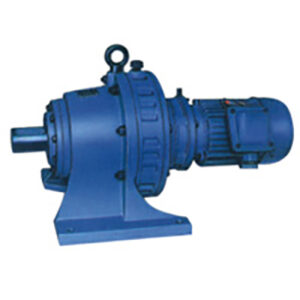
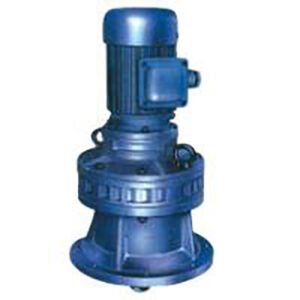
XL BL Series Cycloidal Gearbox Single Stage Vertical Flange-mounted
Overview of XL BL Cycloidal Gearbox
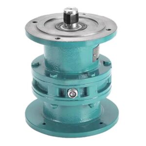
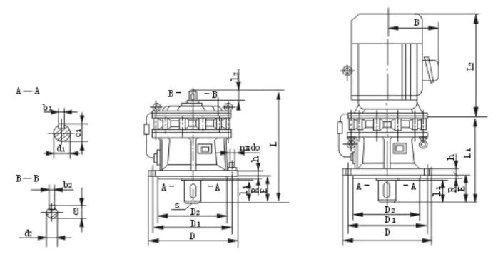
XL BL Series Cycloidal Gearbox Mounting Dimension
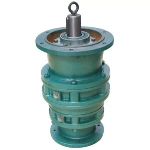
 XL Series Cycloidal Gearbox
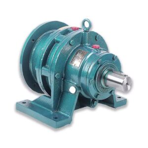
BL Series Cycloidal Gearbox
What Can a Cycloidal Gear Used for?
The cycloidal pin gear reducer adopts the cycloidal pin gear meshing and planetary transmission principle, so it is also commonly called the planetary cycloidal reducer. The planetary cycloidal pin gear reducer can be widely used in petroleum, environmental protection, chemical industry, cement, transportation, textile, pharmaceutical, food, printing, lifting, mining, metallurgy, construction, power generation and other industries, as a driving or reducing device. The machine is divided into horizontal, vertical, double shaft and direct connection types. Its unique stable structure can replace ordinary cylindrical gear reducer and worm gear reducer in many cases. Therefore, planetary cycloidal pin gear reducer is widely used in various industries and fields, and is widely welcomed by users.
Airport logistics
|
Chemical Industry
|
Water Treatment
|
Installation and maintenance of Cycloidal Gearbox
-
When installing coupling, belt pulley, sprocket and other connecting parts on the output shaft of the cycloidal reducer, it is not allowed to use the direct hammering method. Because the output shaft structure of the reducer cannot bear the axial hammering force, the connecting parts can be pressed by screwing in the screw hole at the shaft end.
-
The diameter of output shaft and input shaft shall be matched with GB1568-79.
-
The eyebolts on the reducer are only for lifting the reducer.
-
When installing the reducer on the foundation, calibrate the elevation of the installation center line, levelness and relevant dimensions of the connected parts of the reducer. The concentricity of the calibrated installed shaft shall not exceed the allowable range of the coupling.
-
When the reducer is calibrated, steel or cast iron cushion blocks can be used. The height of the cushion blocks shall not exceed three, or the wedge iron can be used. However, the flat cushion blocks shall be replaced after the reducer is calibrated.
-
The cushion blocks shall be arranged symmetrically on both sides of the foundation bolts to avoid deformation of the machine body, and the distance between them shall be enough to allow free flow of water slurry during irrigation.
-
The irrigation of cement slurry shall be dense and free from bubbles, voids and other defects.
Lubrication
-
The horizontal cycloidal reducer adopts oil pool lubrication under normal conditions, and the oil level can be kept in the middle of the oil window. When the working conditions are bad and the ambient temperature is high, the circular lubrication can be used.
-
The cycloidal pin gear reducer is generally lubricated with 40 # or 50 # machine oil at normal temperature. In order to improve the performance of the reducer and prolong the service life of the cycloidal pin gear reducer, 70 # or 90 # extreme pressure gear oil is recommended. The lubricating oil can also be re considered when working at high and low temperatures.
-
When the planetary cycloidal pin gear reducer is installed vertically, the oil pump shall be strictly prevented from cutting off oil to avoid damage to the reducer components.
-
To refuel, unscrew the vent cap on the upper part of the engine seat. When draining the oil, unscrew the oil drain plug at the lower part of the engine seat to drain the dirty oil. There is no lubricating oil inside the reducer when it leaves the factory.
-
The oil shall be replaced after the first refueling operation for 100 hours. (The internal dirty oil shall be flushed clean) Then the oil shall be continuously operated. The oil shall be replaced every half a year (8 hour working system). If the working conditions are bad, the oil change time can be appropriately shortened. Practice has proved that regular cleaning and oil change of the reducer (such as 3-6 months) play an important role in extending the service life of the reducer. The lubricating oil shall be replenished frequently during use.
-
The ex factory reducer has been greased and replaced every six months. Aluminum disulfide – 2 # or 2L-2 # lithium base lubricating grease shall be used.

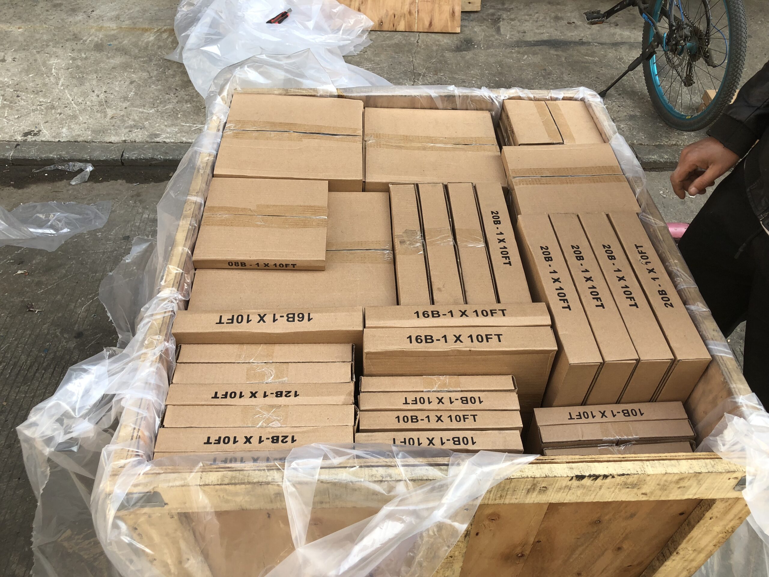
Packing Shipping Delivery
  |
 |
|
 |
 |
|
How to choose power transmissions parts and industrial products which meet our requirement
| Chains | Sprockets | Pulleys | Timing belt Pulley | V-belt Pulley |
| Sheaves | Coupings | Bush &Hub | Gear& Rack | V-Belt |
| Locking Assembly | Pulley | Gearbox | Reducer | Shaft Collar |
| Rod End Bearing | Clevis | PTO | Chain Guide | Belt Guide |
| Rubber Buffer | Chain Tensioner | PTO Drive Shafts | Universal Joints | Roller Chains |
| Conveyor Chains | V-Belts | Worm Gearbox | Helical Gear | Worm |
| Agricultural Chain | CNC Proces Parts | Casting | Stamping | |
| Powder Metallurgy | CNC Proces Parts | Casting | Stamping |
What Products Do you sell ?
We are a group of factories, give customer one stop solution of power transmission and industrial products. We are in the position to supply wide range of products, including chains, sprockets, v-belt and v-belt pulleys, timing belt and timing belt pulleys, gears, speed reducers, motors, racks, couplings, and many other parts, like locking assembly, taper bushing, Chain guide, shaft collar, torque limiter, cam clutch, universal joint, motor base and motor slide, rod end, clevis, rubber mount, etc. We make special parts according to drawings and/or samples.
How to choose a gearbox which meets our requirement?
You can refer to our catalogue to choose the gearbox or we can help to choose when you provide
the technical information of required output torque, output speed and motor parameter etc.
What information shall we give before placing a purchase order?
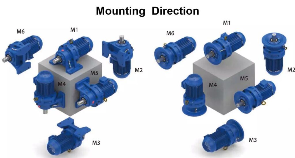
a) Type of the gearbox, ratio, input and output type, input flange, mounting position, and motor informationetc.
b) Housing color.
c) Purchase quantity.
d) Other special requirements.
What industries are your gearboxes being used?
Our gearboxes are widely used in the areas of textile, food processing, beverage, chemical industry,
escalator,automatic storage equipment, metallurgy, tabacco, environmental protection, logistics and etc.
What is the producing process?
Production process including raw material cutting, machine processing, grinding, accessories cleaning, assemble, cleaning, stoving, oil coating, cover pressing, testing, package.
How to control the products quality?
Combining advanced equipment and strict management, we provide high standard and quality bearings for our customers all over the world.
What is the transportation?
-If small quantity , we Suggest to send by express, such as DHL,UPS, TNT FEDEX. If large amount, by air or sea shipping.
Can we design packaging?
-Yes. Default is regular packing, and we can make customer's own packing.
Can you provide OEM service?
-Yes, we work on OEM orders. Which means size, quantity, design, packing solution, etc will depend on your requests; and your logo will be customized on our products.
Can you give me discount on Power Transmissions Parts and Industrial parts?
-Yes, of course. Pls. send me your Email, you'll get more
Q: Are You a trading company or a manufacturer?
A: We Are the factory and have our Own trading company
Q: How Can I get an offer?
A: please send US quotation information: drawings, materials, weight, quantity and requirements, we can accept PDF, ISGS, DWG, STEP file format. If you don't have the drawings, please send us the samples, we can also quote you according to your samples.
Q: What is your minimum order size?
A: it is usually 100 pieces, but a low quantity is acceptable under some special circumstances.
Q: Do you provide samples? Is it free or extra?
A: Yes, we can provide samples free of charge, but we don't pay the freight.
Q: What is the lead time for mass production?
A: honestly, it depends on the number of orders. Normally, if you don't need the tools, deposit them after 30 days or so.
Q: What if the parts don't Work?
A: we can guarantee the quality, but if it happens, please contact us immediately, take some photos, we will check the problem and solve it as soon as possible.
Q: What are your terms of payment?
A: payment is less than US $1000,100% in advance. Payment: $1000,50% wire transfer in advance, balance before shipment,Other Terms of payment are negotiable


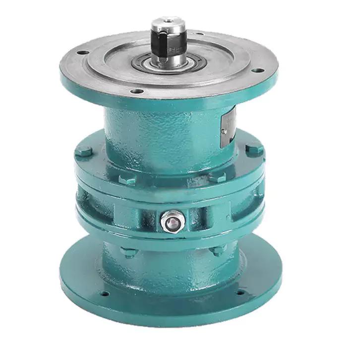
 XL Series Cycloidal Gearbox


Reviews
There are no reviews yet.