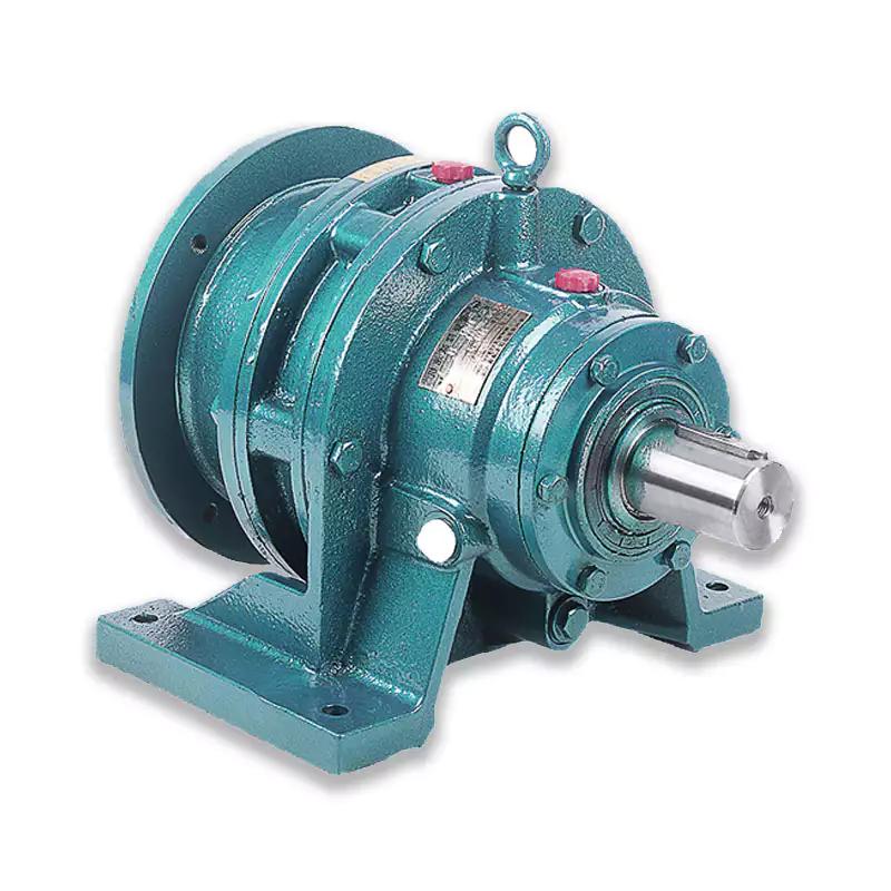
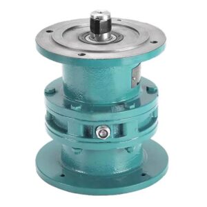
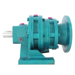
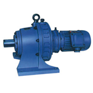
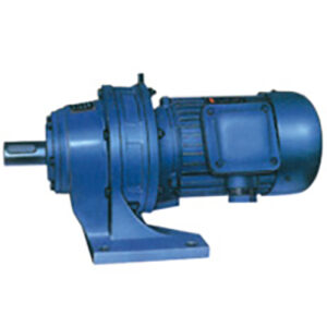
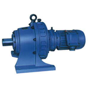
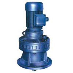
XW BW Series Cycloidal Gearbox Cyclo Pin Wheel Reducer Single Stage Horizontal Foot-Mounting
Overview of XB Cycloidal Gearbox
The cycloidal pin gear reducer is a transmission model based on the principle of cycloidal pin gear meshing planetary transmission. It is an ideal transmission device with many advantages, wide use, and positive and negative operation
XW BW Series Cycloidal Gearbox Characteristic
- High-speed ratio, large torque, high efficiency, averaging 95%
- Compact structure and small volume
- Stable operation and low noise
- Few failures and long service life.
Structure and principle
Cycloidal pin gear reducer is a planetary transmission principle using cycloidal gear meshing. A 180 ° eccentric sleeve is installed on the input shaft, and two roller bearings are installed on the eccentric sleeve to form the H mechanism. The center holes of the two cycloidal gears form the raceway of the eccentric bearing. The cycloidal gear is meshed with a group of needle teeth on the needle gear to form an internal meshing reducer with a tooth difference.
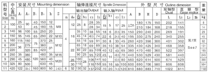
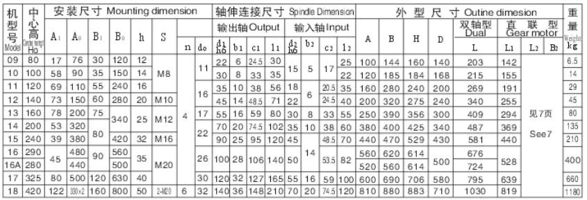
XW BW Series Cycloidal Cyclo Pin Wheel Gearbox Dimension
XW Series Cycloidal Gearbox
 BW Series Cycloidal Gearbox
Our Cycloidal Reducer Feature
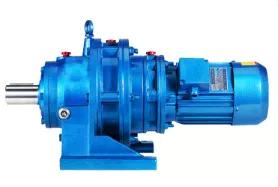 |
Reducer body The body is made of thickened material, and the reducer surface is more clean, smooth and durable through professional polishing technology. |
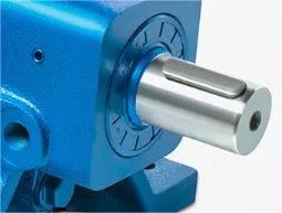 |
Output shaft of reducer High hardness shaft, multiple precision machining, smooth and flat appearance, not easy to damage the seal ring, easy to install, and ensure the smooth operation of the reducer. |
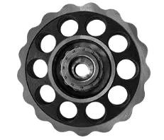 |
New accessories The reducer uses brand new accessories, high-quality materials, high hardness and stable performance. |
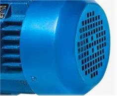 |
Reduce noise Low noise, large overload capacity and strong shock resistance. |
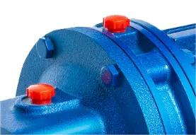 |
Filler hole B0/X2 and B1/X3 have been greased, B2/X4 and above models have not been added, please add oil before use. |
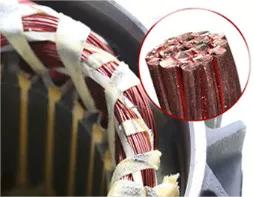 |
Copper coil The reducer can be matched with the national standard/directly connected motor. The motor adopts a new copper core coil to make the motor more stable, efficient and safe. |
How to Select Cycloidal Reducer(XW BW Series Cycloidal Gearbox)
There are many factors to consider when choosing a cycloidal reducer that suits you. Today, we will pick out some of the more important factors to share with you.
In addition to the technical requirements for selecting the reducer, what other requirements are there? Some of the more common methods are discussed below.
Ambient temperature
- An important but sometimes overlooked factor is temperature. For example, the motor rating is based on a certain ambient temperature, usually 40 ° C. If the application is continuous operation with high ambient temperature, motors with rated torque higher than the calculated value may be required.
Duty cycle
- For the motor and cycloidal reducer, the duty cycle will affect the temperature rise of the motor and affect the gear wear rate. If the application has intermittent duty cycles, motors with rated torque lower than the calculated value may be used. However, frequent starting and stopping will reduce the expected life of the gear. This is also related to the service factors published by gear manufacturers in their catalogues.
Overall dimensions
The shape factor is another parameter that affects the operation. For example, when using a DC motor speed controller, the shape coefficient of the controller’s output DC voltage will affect the motor size and transmission ratio, and whether cycloidal reducer is required. One factor in increasing motor temperature is unfiltered control. This means that a larger motor than calculated may be required, especially if the duty cycle is continuous. The speed of the motor will also slow down, because this control has a lower output voltage than the filter control. This is why it is so important to use the correct motor speed when calculating the transmission ratio.
Radial and axial loads
The load also affects the motor bearings. In particular, motors have different types and sizes of bearings, and each bearing has different radial and axial load capacities. Also, depending on the load capacity, a larger motor than calculated may be required. For example, applications with high radial loads, such as pinch rolls and belt drives, may require larger motors. However, high axial loads, such as lead screws, may also be applied, and larger motors may be required. In this sense, bigger means a stronger motor, not necessarily more output power.
How does a Cycloidal Gearbox Work?
A unique principle of cycloidal gears is that the outer circle used to form the top tooth surface (epicycloid) of one gear is used as the inner circle used to form the root tooth surface (hypocycloid) of another gear. This ensures a constant angular velocity and supports the basic law of gear transmission. That is, the angular velocity ratio of a gear must remain constant throughout gear engagement.
Cycloidal gear box uses the principle of cycloidal gear to provide high transmission ratio (usually 100:1 or higher), with excellent torsional stiffness, good impact load capacity, stable backlash and low wear within the service life of the gear box.
Cycloidal gear box has many designs, but its basic principle is composed of an input shaft eccentrically mounted on a driving member or bearing, which drives the cycloidal disk with eccentric motion. When the disc rotates, the convex angle of the cycloidal disc is like a tooth, which meshes with the pin on the fixed gear ring. The cycloidal disc also has roller pins projecting through the disc. Which are connected to the output disc, which transmits motion to the output shaft.
The number of convex angles (teeth) on the cycloidal disk is lower than the number of pins (teeth) on the ring gear, so as to achieve deceleration and torque multiplication. To prevent the output shaft from “swinging”, the roller pin connected to the output plate is installed in a hole slightly larger than the pin diameter. A single cycloidal disc bears the unbalanced force, which can be compensated by using a second cycloidal disc (offset by 180 degrees from the first cycloidal disc).
Cycloidal gear is more difficult to manufacture than involute gear, which requires extremely accurate manufacturing and assembly. But they do provide significant benefits in some applications. First, they can provide transmission ratios up to 300:1 in relatively small packages. Especially in terms of gearbox length, because they do not need to “stack” gear stages like planetary designs.
Because of its rolling contact and lower Hertz contact stress, the friction and wear of cycloidal gears on the tooth surface are also lower. Its good torsional stiffness and the ability to withstand impact load make it an ideal choice for heavy industrial applications requiring servo accuracy and stiffness.

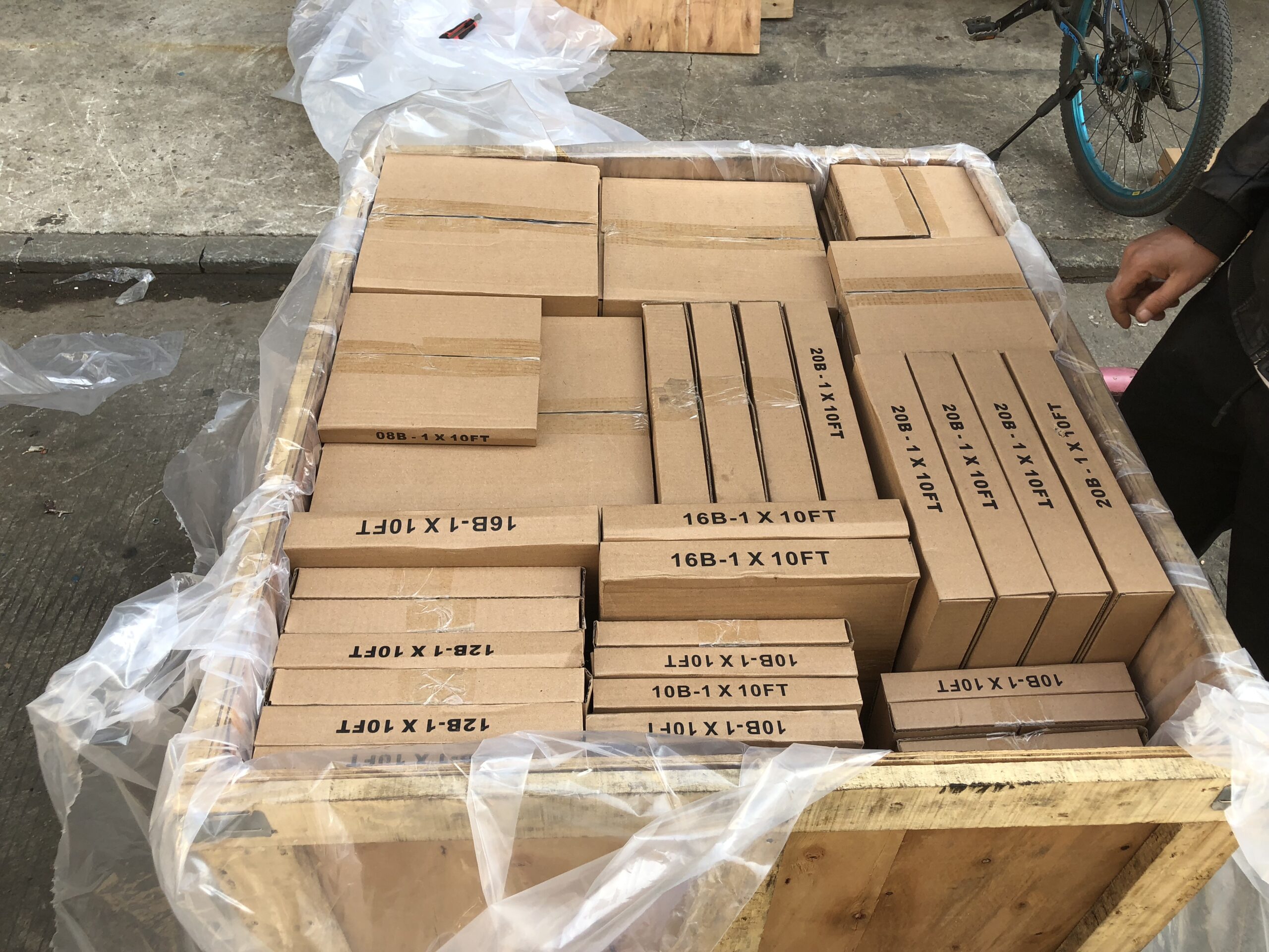
Packing Shipping Delivery
  |
 |
|
 |
 |
|
How to choose power transmissions parts and industrial products which meet our requirement
| Chains | Sprockets | Pulleys | Timing belt Pulley | V-belt Pulley |
| Sheaves | Coupings | Bush &Hub | Gear& Rack | V-Belt |
| Locking Assembly | Pulley | Gearbox | Reducer | Shaft Collar |
| Rod End Bearing | Clevis | PTO | Chain Guide | Belt Guide |
| Rubber Buffer | Chain Tensioner | PTO Drive Shafts | Universal Joints | Roller Chains |
| Conveyor Chains | V-Belts | Worm Gearbox | Helical Gear | Worm |
| Agricultural Chain | CNC Proces Parts | Casting | Stamping | |
| Powder Metallurgy | CNC Proces Parts | Casting | Stamping |
What Products Do you sell ?
We are a group of factories, give customer one stop solution of power transmission and industrial products. We are in the position to supply wide range of products, including chains, sprockets, v-belt and v-belt pulleys, timing belt and timing belt pulleys, gears, speed reducers, motors, racks, couplings, and many other parts, like locking assembly, taper bushing, Chain guide, shaft collar, torque limiter, cam clutch, universal joint, motor base and motor slide, rod end, clevis, rubber mount, etc. We make special parts according to drawings and/or samples.
How to choose a gearbox which meets our requirement?
You can refer to our catalogue to choose the gearbox or we can help to choose when you provide
the technical information of required output torque, output speed and motor parameter etc.
What information shall we give before placing a purchase order?
a) Type of the gearbox, ratio, input and output type, input flange, mounting position, and motor informationetc.
b) Housing color.
c) Purchase quantity.
d) Other special requirements.
What industries are your gearboxes being used?
Our gearboxes are widely used in the areas of textile, food processing, beverage, chemical industry,
escalator,automatic storage equipment, metallurgy, tabacco, environmental protection, logistics and etc.
What is the producing process?
Production process including raw material cutting, machine processing, grinding, accessories cleaning, assemble, cleaning, stoving, oil coating, cover pressing, testing, package.
How to control the products quality?
Combining advanced equipment and strict management, we provide high standard and quality bearings for our customers all over the world.
What is the transportation?
-If small quantity , we Suggest to send by express, such as DHL,UPS, TNT FEDEX. If large amount, by air or sea shipping.
Can we design packaging?
-Yes. Default is regular packing, and we can make customer's own packing.
Can you provide OEM service?
-Yes, we work on OEM orders. Which means size, quantity, design, packing solution, etc will depend on your requests; and your logo will be customized on our products.
Can you give me discount on Power Transmissions Parts and Industrial parts?
-Yes, of course. Pls. send me your Email, you'll get more
Q: Are You a trading company or a manufacturer?
A: We Are the factory and have our Own trading company
Q: How Can I get an offer?
A: please send US quotation information: drawings, materials, weight, quantity and requirements, we can accept PDF, ISGS, DWG, STEP file format. If you don't have the drawings, please send us the samples, we can also quote you according to your samples.
Q: What is your minimum order size?
A: it is usually 100 pieces, but a low quantity is acceptable under some special circumstances.
Q: Do you provide samples? Is it free or extra?
A: Yes, we can provide samples free of charge, but we don't pay the freight.
Q: What is the lead time for mass production?
A: honestly, it depends on the number of orders. Normally, if you don't need the tools, deposit them after 30 days or so.
Q: What if the parts don't Work?
A: we can guarantee the quality, but if it happens, please contact us immediately, take some photos, we will check the problem and solve it as soon as possible.
Q: What are your terms of payment?
A: payment is less than US $1000,100% in advance. Payment: $1000,50% wire transfer in advance, balance before shipment,Other Terms of payment are negotiable


 BW Series Cycloidal Gearbox
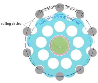 A unique principle of cycloidal gears is that the outer circle used to form the top tooth surface (epicycloid) of one gear is used as the inner circle used to form the root tooth surface (hypocycloid) of another gear. This ensures a constant angular velocity and supports the basic law of gear transmission. That is, the angular velocity ratio of a gear must remain constant throughout gear engagement.
Reviews
There are no reviews yet.